Saturday, January 19, 2013

Reusing the RAD 1.0, 2.0 remote control system


The RAD remote control system is a very robust RC system that is easy to adapt to many RC vehicles and for custom made robots.   The system consists of a dual joystick remote control with microphone and a receiver board that can directly drive 4 motors forward and reverse and one motor on and off. Plus you can turn a light off and on and turn the speaker off an on (normally it idles with a simulated engine sound and it makes movement announcements like "arms closing, beep beep").  By pressing a button on the remote and speaking into it, your voice will come out speaker on the receiver circuit. The voice transmitting mode makes the system ideal for "Talking" robots.  The receiver operates on wide range of 6-10 volts, it was designed to operate on the standard 6 volt TYCO or New Bright rechargeable battery. Those batteries are made up of 5 smaller AA cell size rechargeable, On could make a battery pack from 5 AA batteries or similar total voltage.  Here is the remote and receiver circuit removed and ready to install in a new robot.

The receiver can drive most toy motors of an average of about 2 AMPS. If the motor overloads the receiver board will cut the motor power and make a buzzing noise out the speaker.   The joysticks control 2 motors forward and reverse and buttons control forward and reverse on 2 other motors.  A 5th motor is controlled on and off by a single push button on the remote.  The system has a range of about 75 meters and can be increased by making a longer remote antenna, up to the length of the wire antenna on the circuit board.  Because it has a consumer grade robust receiver you can just wire up your robots or vehicles motors and add 6 volts and test the system right away.  If the speaker buzzes a lot when you operate the motors then they are pulling too much current and are not suitable. This is as long are you supplying a full 6.5 volt battery pack and are using wires no smaller than the wires on the receiver board. A RC car or truck that has lost its remote is easy made to function with this system.  Use joystick controlled wires to connect to the vehicle motor and the other joystick for the steering motor.  In most cases you can just tap into whatever battery was used in the vehicle to power the circuit.   Here is the standard wiring diagram for the reciever circuit.

 The right and left track wires would be considered the main drive motor wires only because they are controlled by the joysticks.  In fact all the circuit outputs are the same components so the power output would be the same for all the motors.  The fire button runs a motor as well but is controlled by a single button (Red labeled FIRE) so it is only on and off.  The direction depends on how it is wired. The only downside to this whole system is a 5 second self test that the circuit does when first turned it.  It opens the arm motor then reverses it (closes arm) then it tests the waist motor as well.  It also announces this over the speaker saying "checking system waist down the speaker can be switched off.  But there is not way out of it doing the self test when you first turn it on.
Otherwise it makes a great RC system ready to operate motors.

RAD 2.0 Teardown Whats Inside?

By all the RAD 2.0 has the greatest numbers out there and is a the all out favorite to hack.  The RAD 1.0 is the same robot, but a year older, with older plastic, yet how it was cared for matters more. Here is a fine pair of RADs.

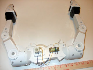
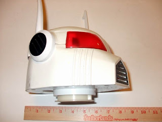
The heads the arms and base track units are easy to remove from a RAD.


And matched remote and receiver pair.

RAD remotes "can they be swapped?"

I have been asked this question many times, "I have a RAD 1.0 and lost the remote, can I use another RAD 1.0 remote that is the same Frequency?"   The short answer is maybe.  In my testing only about 1 in 4 will work with random unpaired remotes and robots.  That is even when all the numbers are the same.  The remote must be the same model robot, a 1.0 for a 1.0 etc.  They will not work across models (the 3.0 and 4.0 have different functions so they would not interchange anyway).  The remote and robot comb must have the same frequency.  This will be either 27Mhz or 49Mhz.  On the robot, it will be on a sticker under the base between the tracks.  On the remote it will be on a sticker on the back of the remote.  These must be the same frequency or it will not work at all.  If these items match then you still got to test it and play the odds of 1 in 4.  Even when I have the proper model and frequency the pair most of the time will just buzz when you move a stick and not actully move a motor.  So its either a case where the remote and receiver pair are fine tuned to each other or just a difference in the circuits with different production runs.  When I tear down these and remove the receiver circuit I find the antenna wire must be the same color as the receiver circuit that it does work with.  So that explains that there is some difference in the circuits that make during a production run of the same model.   So the only way to know for sure is to test a remote and robot together otherwise you are just playing the odds.  

I see single lost RAD remotes sold on eBay all the time just listing the frequency and feel bad for people that purchase them thinking it will make them a functioning pair.  I think many people just buy them and if it does not work they just scratch it up to a bad robot and don't complain.  At one time I threw all my remotes in a box thinking I could sort them later by the frequency stickers.  Instead I must manually test each remote/robot pair before I can begin any project.  I am starting a database to document the circuit revision numbers for comparison of functioning matched pairs, but it would still always test the pair first. I will add to this post as if find a quicker way of knowing a remote/robot pair will work before testing.  I welcome input from others on this as well.
In the end, the remote must be the same model of robot, the same frequency as shown by its sticker and the receiver board must have the same color antenna wire (either red, black, or yellow) however you must also know what the original robots receiver wire color was for that remote.
Was this any help? Just understand when mix them up, and the numbers are the same, I get a 1 in 4 chance of finding a pair that works. 

RAD 4.0 Teardown Whats Inside?

Here are photos of my first RAD 4.0 tear down.  The 4.0 and 3.0 appears to be the same chassis wise and circuit wise as well.  So this will cover the 3.0 dis-assembly as well.  Please forgive the gloomy photos it was late at night.  This view shows all the major circuits inside the 4.0 the large board is the mainboard.  Below that is 2 smaller boards that are just power taps.  2 wires can be seen going into both legs, those are the feet motor wires,  One wire can be seen going into the arm, this is an antenna.   In the head is a small secondary circuit board I think is related to one of the radio circuits.  The zig zag yellow wire in the top of the head is the main radio antenna. Where as the RAD 1.0 and 2.0 had a single circuit board the RAD 3.0 & 4.0 is filled with small circuit boards.  Most are just connect points making it easier to assemble the robot in stages at the factory.

 Here is a close up of the main control board with the miner power connection boards. 


Here is the main board in detail.  If you wanted to build a robot that is voice controlled this is the board you will have to remove below.

You can make a voice controlled robot using just this board, leaving the long antenna wire and the wired microphone that is mounted in the head.   Now for the head.
I believe these boards relate to the secondary Radio that transmits sound from the RAD robot.  These circuits should not be required to make a voice commanded robot.  You should be able to cut these wires and discard the circuits.
 This yellow wire is the antenna mounted in the head.  I think this radio circuit is used by the voice receiver in the RAD.  Again if you are making a voice controlled robot this can be cut out and not needed.

Friday, January 18, 2013

RAD 4.0 Basics

The 4.0 was basically the same as the 3.0 model.   Nothing changed, its the same boring Robot as the 3.0.  It gets stuck in carpet, its remote is flaky and you lucky if you find one that works.  I actually think this design is what ended the series of RADs.  This is the one that lead to the loss of interest in RAD Robots.  Plus the fact that as a robot chassis you could Hack a RC car robot together that would be much more useful.   The control circuit is of at least a little use.   The circuit could be removed, and the drive motor wires could be connected to different dual motor drive system.  You could then just speak commands to the circuits microphone and have a voice activated robot.  All you would have to do is power the circuit with 6 volts and make the microphone was mounted where it would hear you.   
Hacking the 4.0 body into something useful would be about as much work as building a robot from scratch.  The arms are not jointed so to power them and make them flex at the wrist would be same amount of work as just making them from wood.  The shoulder joint is movable but mounting a motor would be a lot of work, just to use the shell of a the arm.  The grippers are just spring loaded.  Again they look cool, but you would have to move the spring and add a way to power them.  The hinge joint on the gripper is weak would have to be beefed up to put up to powered use.   You would have to just attach the ends of the grippers to whatever you construct, because very little is there that can made into a powered gripper unit.  


RAD 3.0 Basics

The RAD 3.0 was a new design with a new voice recognition system for speaking commands to the robot.  There is also a remote but for some reason a large number of these stop working.   Maybe thats why there is the voice recognition system.   It does give you some way to control the robot even without the remote.   I have found many of these missing the remote and only found a few that the remote still work.   The worst thing about the 3.0 and 4.0 is that they are not really very mobile.   There is tiny motorized wheels under the feet that barely operate on a smooth floor.  Moving from smooth floor to rug or just crossing doorway thresholds scags up the robot every time.   This is a long way from the mobility of the RAD 1.0 and 2.0 with its track drive.   The earlier models could go in every room of the house and could adventure outdoors as well. The 4.0 can not operate on dirt, grass or anything that is not hard and smooth.  From a hacking standpoint there is not a lot of value in the robots chassis itself because it does not have any motorized parts.  It looks cool but the hands and arms do nothing so basically its just a shell.   The simplest first hack for this model is to change the drive system.   It would at least make the toy fun to play with.   What is one of the best universal drive systems out there?  You got it, the track drive off of a RAD 1.0 or 2.0!  So an easy hack would be to hack off the 3.0 feet and mount a track drive unit from an earlier model.   There are 2 wires going down the legs in the motors in the feet, attaching these to the each drive motor in the tracks would give you a voice activated system that can go places.   I will tackle the drive system change-out hack in a later posting.


RAD 2.0 Basics

RAD 2.0 overview
The RAD 2.0 was the Second in the series of RAD robots. It really is a great platform for many types of robot mods and do it yourself customization. They come up on eBay from time to for under $100. Please check eBay seller Vintage Electronics by expresshop he always has a few for sale or can post a new listing of any one you want if you ask. They come with a remote control that allows a great deal of freedom of movement. The tracks can be controlled, left, right, forward, reverse and you can rotate robot in both directions. The arms can move in together and out. The hips are controlled so the robot and bend down and pick up items off the floor. As a bonus you can press a button and your voice will be transmitted to a speaker in the robot and you can talk out of the robot. The robot is powered by a very common 6 volt rechargeable battery and remote takes a 9 volt.
The radio receiver is in the head so opening the head and replacing the radio unit with your own controller is a simple operation. All the motor wires and power wires run all the way to the top of the robot.